Welcome to my model train Blog. (2017)
Do you have a (N) scale, or (HO) scale, or (O) scale Atlas turntable?
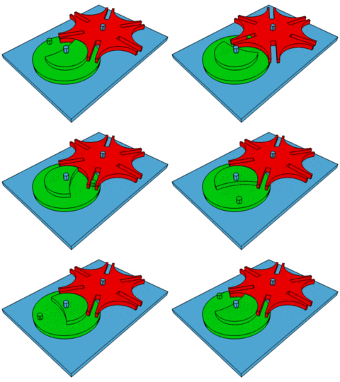
How does an Atlas turntable actually function?
Under the Atlas turntable rotating disk, there is a Geneva movement cam drive system.
* The Atlas 12.V-DC motor is always turning.
* At the delayed required index location the 12.V-DC motor is turned "Off".
How the Atlas turntable indexes is an excellent simple procedure. Between the turntable rotating disk and the support base, there are open gaps. These open gaps will allow small foreign debris to fall into the Geneva movement causing indexing problems. Periodically remove the turntable rotating disk and check for any foreign debris that could effect the function of the Geneva movement.
The Atlas turntable is powered by an Atlas 12.V-DC electric motor.
The older electric motors used multiple gears and the newer electric motors now use a belt drive for a quieter operation. The electric motor sounds will vibrate into the plastic turntable frame work, because the electric motor is solidly mounted to the turntable frame work. There are also several internal operating gears and a rotating cam that will also make some noise. Adding model train gear grease to the internal gears will slightly quiet down the unwanted noise. Using gear grease will make it much more difficult to find and clean any foreign debris in the Geneva movement.
Why not mask over the unwanted turntable sound by adding a turntable sound module?
Since the Atlas 12.V-DC electric motor is constantly turning (powered) from start to finish during turntable rotation, a turntable sound module can be easily added.
ITT Products makes many different types of sound modules. (www.ittproducts.com/).
ITT Products <<< (Mouse Click To Link)
GL320-1 = Turntable 1 (Sound)
GL320-1 = Turntable 1 <<< (Mouse Click To Link)
GL320-2 = Turntable 2 (Sound)
GL320-2 = Turntable 2 <<< (Mouse Click To Link)
Special Note:
Some of the first releases of the New (GL) series (2018) have polarity (+) and (-)
marked on the circuit board for (V-DC) power input.
George from ITT Products has informed me that the (+) and (-) polarity markings
can be ignored. Parity does Not matter.
Digital Command Control (DCC):
- OR-
Digital Command System (DCS):
- OR -
(V-DC) Track
Option (#1)
* (DCC) or (DCS) or (V-DC) will control the turntable track power supply
* Require a separate 12.V-DC power supply (1.Amp) to power turntable motor and sound module
* The D.P.D.T. (center off) switch controls rotation directions and stop rotation position
* Recommend using (1) high quality wire terminal to insure excellent wire connections (x6)
* The D.P.D.T. (center off) switch also turns the sound module On and Off
* A safety feature adding a D.P.D.T. (Track) switch to control the turntable track power supply
* Still using same the (12.V-DC) power supply
* A bi-polar (5.MM .196") Red and Green LED to indicate turntable track power supply
* LED Red = track power OFF* LED Green = track power ON
* A required resistor (R1) is required when using an LED
* Recommend using (2) high quality wire terminals to insure excellent wire connections (x12)
Required (R1) resistor calculation.
Example:
* Bi-polar (5.MM .196" Dia.) LED
* Rated at 2.2 V-DC
* Rated at 20mA maximum
LED Resistor Calculator
LED - Resistor Calculator: <<< (Mouse Click To Link)
[12] Source voltage
[2.2] diode forward voltage
[20] diode forward current (mA)
Speaker Also Required:
Use a 4" inch (square flanged) 8 Ohm speaker, for much better sound quality and much easier to mount facing down under the turntable. Use small stacked rubber "O" rings between the speaker flange and wooden mounting surface to prevent sound vibrations. Also mount the speaker as close as possible under the turntable, facing down. When using a single speaker, correct speaker polarity is "not" important.
© 2017 ITT Products (www.ittproducts.com/). ITTP Images and Sounds
Posted by Grand Trunk Railway Systems at Sept. 01 2017


